Getting Started with ZigBee
ZigBee is a low power, wireless mesh network standard. It is used in home automation, medical data collection, industrial control, etc.
This article is a first in a series of articles explaining the ZigBee protocol. We start with an introduction to various components of a ZigBee network. The article explains the components using a series of example network configurations, with increasing complexity.
Two Node Network
A simple two node ZigBee network is shown in the following diagram.
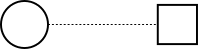
The node shown as a circle, is the coordinator. The coordinator, performs the following.
-
Selects a radio frequency band for communication within the network.
-
Selects a unique no. to identify the network, called the Personal Area Network ID (PAN ID).
The node shown as a square, is the end device. The end device is a sensor/controller that uses the wireless network for data transmission/reception. The end device joins the network formed by the coordinator, and then can communicate with the coordinator.
Multi-Node Network
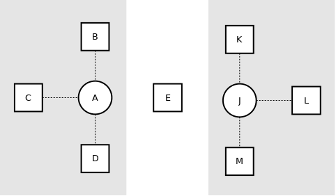
The above network can be extended by adding any number of end devices.
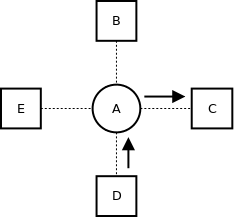
It should be noted that, even though the end devices are within the range of communication, they do not talk to each other directly. The end devices can send and receive data only through the coordinator (or router, more on this later). When the node D wants to send a message to C, it sends the message to the coordinator A, which then forwards the message to C. Thus the coordinator also plays the role of routing packets between the end devices.
Extended Range
The maximum indoor range is between 40m - 90m, depending upon the module. But this range can be extended by using routers as shown in the following diagram.
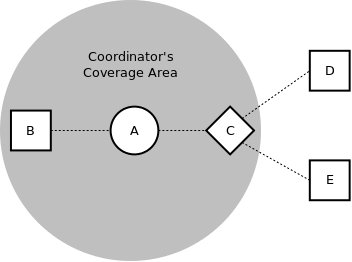
The node shown as a diamond, is the router. The router joins the network formed by the coordinator. After joining a network, the router also allows other end devices within its range to join the network. The router in addition to sending and receiving its own data, can also act as intermediate passing data from other nodes.
Nodes D and E, join the network through the router C. Even though nodes D and E are not within the coverage area of A. A can send and receive data through router C, which has A, D, and E in its coverage range.
Redundant Paths
In the previous network, if the router C, fails then D and E, gets disconnected from the network. This problem can be avoided by having multiple routers that link the end devices to the network. A network with redundant routers, is shown in the following diagram.
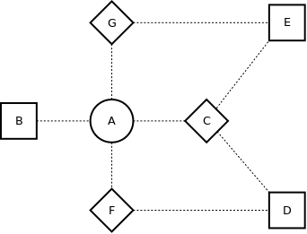
In the above network, node A can reach E, through C and G. The network chooses and utilizes the most optimal path by default. If for example, the path through C is the most optimal path, the data will be routed through C to E. If the node C fails, the network detects the failure, and re-routes the data through G, which is the next most optimal path. Thus the ZigBee network can be made self-healing, using redundant paths.
Multiple Networks
So far, we have assumed that there was only one ZigBee network. ZigBee is designed to work even when there are multiple co-located ZigBee networks.
Multiple networks are isolated by the fact that they have different PAN IDs, and use a different radio frequency band. As previously discussed, the coordinator chooses a unique PAN ID not used by a neighbouring network and a radio frequency band that has the lowest power.
The situation is slightly complicated for routers and end devices. In the above network when the node E, starts up it sees two ZigBee networks. The node E might join any one of the networks, using two mechanisms:
-
Fixed PAN ID
-
Permit Joining
In the fixed PAN ID method, the router/end device is configured with a PAN ID. The router/end device will only join a network that corresponds to the configured PAN ID.
In the permit joining method, the coordinator and routers in a network permit joining only for a fixed period of time. Any router/end device that tries to join the network after the join period, will not be allowed to join a network. So even if there are multiple networks, and only one of the networks permits joining, a router/end device will join the network that permits joining.
Sleeping End Devices
Each end device has a parent (router/coordinator), that allowed the end device to join the network. The end devices always send and receive data through the parent device.
End devices in ZigBee are designed to be battery powered. The end devices can conserve power by entering sleep modes. End devices cannot receive data when they are in sleep mode. When in sleep mode, the parent of the end device buffers the data destined to the end device. The sleeping end device wakes up periodically and polls the parent for any buffered data.
This mode of sleeping is called a cyclic sleep. Cyclic sleep can improve battery life from a few months, to a few years.
Conclusion
In short, ZigBee defines three types of devices: coordinator, router and end device.
- Coordinator
-
-
Selects a radio frequency band and PAN ID.
-
Allows routers and end devices to join the network.
-
Assists in routing data.
-
Is powered from mains and cannot sleep.
-
Buffers data packets for sleeping child end devices.
-
- Router
-
-
Joins a ZigBee PAN before it can transmit, receive, or route data.
-
Allow routers and end devices to join the network.
-
Assists in routing data.
-
Is powered from mains and cannot sleep.
-
Can buffer RF data packets for sleeping child end device.
-
- End Device
-
-
Joins a ZigBee PAN before it can transmit or receive data.
-
Allows devices to join the network.
-
Always transmits and receives data through its parent.
-
Does not route data.
-
Enters sleep mode to conserve power and hence can be battery-powered.
-