Stepper Motor Board with ZDev
In this second installment, in the stepper motor series, sample code is provided to control the stepper motor using the ZDev library.
Hardware Components
-
Stepper Motor Board
-
ZKit-ARM-1343 Board
-
Stepper Motor
-
12V Power Supply
Hardware Setup
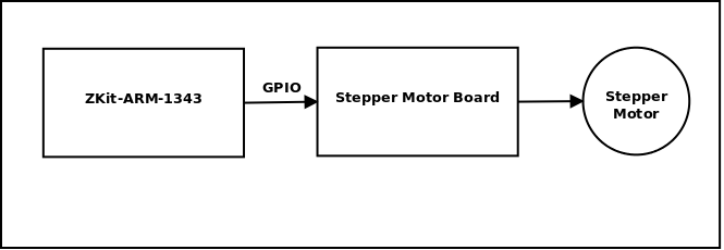
-
Connect the Stepper Motor Board to the ZKit-ARM-1343 board’s DIO header.
-
Connect the Stepper Motor to the Stepper Motor Board
-
Connect the 12V supply to the Stepper Motor Board.
Software
#include <board.h>
#include <gpio.h>
#include <delay.h>

#define MAX_PIN 4
#define ON 1
#define OFF 0

int pins[] = {GPIO2_0, GPIO2_2, GPIO2_1, GPIO2_3};

void stepper_init(void)
{
        int i;

        for (i = 0; i < MAX_PIN; i++) {
                gpio_enable_pin(pins[i]);
                gpio_direction_output(pins[i], OFF);
                gpio_set_pin(pins[i], OFF);
        }
}

int main(void)
{
        int i, j;

        board_init();
        delay_init();
        gpio_init();

        stepper_init();

        i = 0;
        j = 1;

        while (1) {
                gpio_set_pin(pins[i], ON);
                gpio_set_pin(pins[j], ON);

                mdelay(1000);

                gpio_set_pin(pins[i], OFF);
                gpio_set_pin(pins[j], OFF);

                i = (i + 1) % MAX_PIN;
                j = (j + 1) % MAX_PIN;
        }

        return 0;
}
ZKit-ARM-1343 GPIO pins mapping for each of the stepper motor signals is shown in the following diagram.
| Pin No. | GPIO pins | Phase |
|---|---|---|
0 |
GPIO2_0 |
|
1 |
GPIO2_1 |
|
2 |
GPIO2_2 |
|
3 |
GPIO2_3 |
|
The pin mapping is stored in an array pins, so that it can be easily
iterated over.
In stepper_init(), the pins are configured for GPIO functionality,
GPIOs direction is set to output.
In the infinite while loop in main(), the stepper motor is driven
in full stepping sequence. The sequence table is given below. The
phases indicated with a *, are driven 12V, while the other phases are
connected to ground.
| Pin No. | Phase | Step 1 | Step 2 | Step 3 | Step 4 |
|---|---|---|---|---|---|
0 |
|
* |
* |
||
1 |
|
* |
* |
||
2 |
|
* |
* |
||
3 |
|
* |
* |
Initially pins 0 and 1 are selected. Within the while loop,
-
The selected pair of pins is turned ON.
-
A short delay, determines the speed of rotation.
-
The selected pair of pins is turned OFF, to prepare for the next step.
-
The next pair of pins is selected based on the sequence table.
Concluding Notes
Hope this article has helped to understand, how to use Stepper Motor Board with the ZDev library.
Related Articles
Credits
-
The stepper motor icon is based on the original image located here, at Wikimedia Commons.