Stepper Motor, Getting Started
Stepper motors are used in a wide variety of applications, including computer peripherals like printers, scanners, CD drives, camera lenses, etc. In this first article, in a series of articles on stepper motors, we will introduce the reader to the theory behind the working and control of a stepper motor.
Stepper Motor Basics
A Stepper Motor just like any other motor, converts electrical energy into mechanical energy. A stepper motor consists of the following parts:
- Stator
-
The stationary part of the motor. In a stepper motor, the stator is a set of electromagnets.
- Rotor
-
The non-stationary part of the motor. In a stepper motor, the rotor is a permanent magnet.
The arrangement of the electromagnets and the permanent magnets in a simple stepper motor is shown in the following diagram.
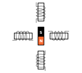
Stepper Motor Operation
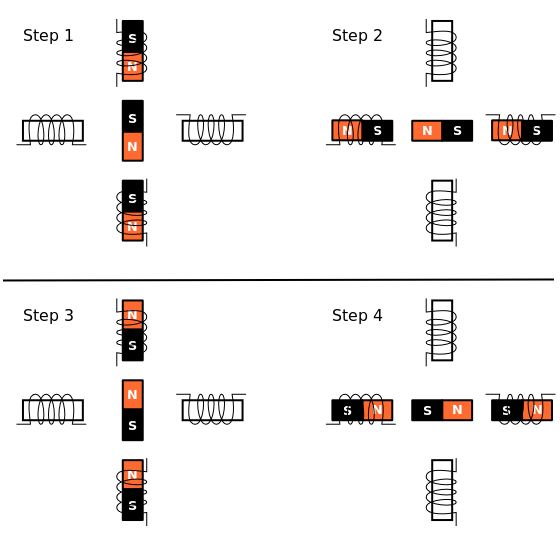
When each of the electromagnet pairs is energized successively, the permanent magnet is attracted to the electromagnet, and aligns with it. This results in rotation of the permanent magnet. This is illustrated in “Stepper Motor Operation” diagram. The stepper motor gets its name from the fact that the rotor rotates in discrete step increments.
The simple stepper motor has a step angle of 90 degrees. More complex stepper motors can have step angles as low as 3.6 degrees. These stepper motors have more no. of poles in the rotor.
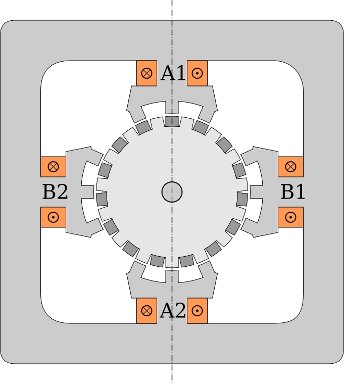
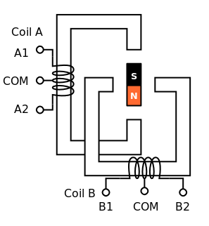
A complex stepper motor is shown in below diagram. The dark grey areas on the rotor are South poles and light grey areas on the rotor are North poles. The stator and the poles are arranged such that, when A1 and A2 is aligned with poles on the stator, B1 and B2 are slightly offset by a small angle from the poles on the stator.
Initially, assume that A1 and A2 are energized such that they form North and South poles, respectively. When B1 and B2 are energized to form North and South poles, the rotor rotates in the anti-clock wise direction, to align with the limbs of the electromagnet. And in the next step A1 and A2 are energized such that they form South and North poles, and so on.
Stepper Motor Winding
The stepper motor is generally constructed using two electromagnets as
shown in below “Bipolar Wound Stepper Motor” diagram. The stepper
motor will have two windings, indicated as A and B. For the
stepper motor, to function, a mechanism should be available to switch
the direction of current flow in the coils. This is required so that
during Step 1, as indicated in “Stepper Motor Operation” diagram, the
current in Coil A flows in one direction, and during Step 3, the
current in Coil A flows in the opposite direction.
Bipolar Stepper Wound Motor
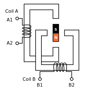
Consider the winding shown in “Bipolar Wound Stepper Motor”. During Step 1, Coil A has to be energized as follows. This will result in the required magnetic poles on the electromagnet.
| Phase | Voltage |
|---|---|
|
12V |
|
Ground |
During Step 3, Coil A polarity has to be reversed. To reverse the poles of the electromagnet, Coil A has to be energized as shown below
| Phase | Voltage |
|---|---|
|
Ground |
|
12V |
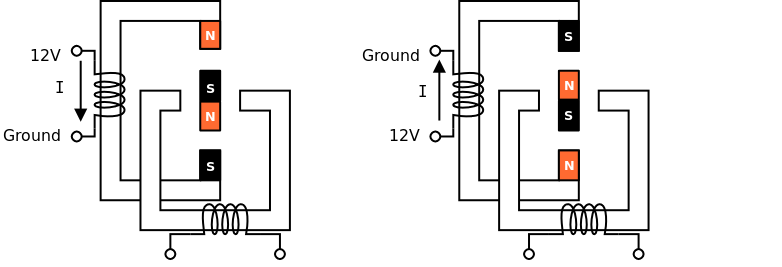
The same applies to Coil B. This type of stepper motor is called Bipolar Wound Stepper Motor.
Unipolar Wound Stepper Motors
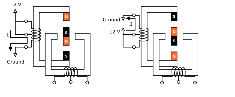
Bipolar Wound Stepper Motors, require additional circuits to reverse the polarity of the coils. To simplify this, another class of stepper motors called Unipolar Wound Stepper Motors, provide an additional center tap in the windings. The center tap is always connected to the power supply, say 12V. With the center tap in place, during Step 1, the phases will be driven as shown below
| Phase | Voltage |
|---|---|
|
12V |
|
12V |
|
Ground |
During Step 3, to reverse the magnetic poles, the phases will be driven as shown below.
| Phase | Voltage |
|---|---|
|
Ground |
|
12V |
|
12V |
Drive Modes
The Drive Mode, indicates the order in which the coils are energized for the stepper motor to complete one turn. For the drive mode shown in “Stepper Motor Operation”, the excitation sequence is shown in the following table. The phases indicated with a *, are driven 12V, while the other phases are connected to ground.
| Phase | Step 1 | Step 2 | Step 3 | Step 4 |
|---|---|---|---|---|
|
* |
|||
|
* |
|||
|
* |
|||
|
* |
This drive mode, is called the Wave Drive. This is the simplest drive mode. The disadvantage is that, in the case of bipolar motors, only 50% of the winding is utilized, and in the case of unipolar motors, only 25% of the winding is utilized.
The Full Step Drive mode, utilizes the 100% of the winding in the case of bipolar motors and 50% of the winding in the case of unipolar motors. The excitation sequence is shown in the following table.
| Phase | Step 1 | Step 2 | Step 3 | Step 4 |
|---|---|---|---|---|
|
* |
* |
||
|
* |
* |
||
|
* |
* |
||
|
* |
* |
Since the winding utilized is higher than the Wave Drive mode, the Full Step Drive mode provides a higher holding torque compared to the Wave Drive mode.
Concluding Notes
Hope this tutorial has helped the novice to come up to speed with stepper motors. In the next article, in this series, we will provide sample code, showing how to control a stepper motor from ZDev, ZIO and NuttX.
Credits
-
The complex stepper motor diagram is based on the original image located here, at Wikimedia Commons.
-
The stepper motor icon is based on the original image located here, at Wikimedia Commons.