Seven Segment Board with NuttX
In this second installment, in the Seven Segment series we are going to see how to interface the Seven Segment Display Board with NuttX. If you haven’t, you might want to read the Seven Segment board fundamentals described in the blog article Seven Segment Board, Getting Started, before reading this article.
Hardware
-
Seven Segment Board
-
ZKit-ARM-1769 Board
Hardware Connections
We don’t have the dedicated 14 pin DIO header in the ZKit-ARM-1769, required for the Seven Segment Board. Hence, we are going to make some hardware setup to connect the Seven Segment board.
We are going to use GPIO pins in I2C and SPI header in order to get the twelve pins connection, 8 pins for data, 3 pins for address and 1 Pin for selection`.
Following table shows the pin connection for seven segment board with ZKit-ARM-1769
| S.No | Description on controller side | Header name | Pin no in Seven Segment board | Signal name in seven segment |
|---|---|---|---|---|
1 |
VCC |
SPI |
1 |
VCC |
2 |
P0.7/SCK1 |
SPI |
2 |
DOUT0 |
3 |
P0.8/MISO1 |
SPI |
3 |
DOUT1 |
4 |
P0.9/MOSI1 |
SPI |
4 |
DOUT2 |
5 |
P0.6/SSEL1 |
SPI |
5 |
DOUT3 |
6 |
P0.4 |
SPI |
6 |
DOUT4 |
7 |
P0.5 |
SPI |
7 |
DOUT5 |
8 |
P4.28 |
SPI |
8 |
DOUT6 |
9 |
P4.29 |
SPI |
9 |
DOUT7 |
10 |
P2.1/RXD1 |
I2C |
10 |
DIN0 |
11 |
P2.0/TXD1 |
I2C |
11 |
DIN1 |
12 |
P0.28/SCL0 |
I2C |
12 |
DIN2 |
13 |
P0.27/SDA0 |
I2C |
13 |
DIN3 |
14 |
GND |
I2C |
14 |
GND |
Software
As per the algorithm given in the "Seven Segment Board, Getting Started" article, we are going to build the software to display a string of digits on the Seven Segment Display Board. To acheive this we are going to implement following functions:
-
sseg_init() -
sseg_set_multi_pins() -
sseg_digits_off() -
sseg_on_digit() -
sseg_putc() -
sseg_puts()
Initialization
In sseg_init() the GPIO pins for data and address lines are
initialized.
Setting Multiple pins
It is required to set multiple GPIO pins in one go, when setting the
digit selection and when driving the segments. The function
sseg_set_multi_pins() allows us to do exactly this.
Digits off
In sseg_digits_off() all seven segment digits are turned off.
Turning on a Segment with a digit
In sseg_on_digit() a partiticular seven segment digit is selected,
by driving the digit selection GPIO pins.
Displaying a digit
In sseg_putc(), a particular seven segment digit is selected and the
segment GPIO pins are driven to shown a number between 0 and 9.
Displaying multiple digits
In sseg_puts(), each character from the specified string is
displayed on the corresponding seven segment digit.
After the digit is displayed, a delay of 2ms is introduced so that the digit is visible for atleast 2ms, before the next digit is displayed.
#include <nuttx/config.h>
#include <chip/lpc17_gpio.h>
#include <stdint.h>
#include <stdio.h>
#include <unistd.h>

/* GPIO configuration */
#define A (GPIO_OUTPUT | GPIO_VALUE_ONE | GPIO_PORT0 | GPIO_PIN7)
#define B (GPIO_OUTPUT | GPIO_VALUE_ONE | GPIO_PORT0 | GPIO_PIN8)
#define C (GPIO_OUTPUT | GPIO_VALUE_ONE | GPIO_PORT0 | GPIO_PIN9)
#define D (GPIO_OUTPUT | GPIO_VALUE_ONE | GPIO_PORT0 | GPIO_PIN6)
#define E (GPIO_OUTPUT | GPIO_VALUE_ONE | GPIO_PORT0 | GPIO_PIN4)
#define F (GPIO_OUTPUT | GPIO_VALUE_ONE | GPIO_PORT0 | GPIO_PIN5)
#define G (GPIO_OUTPUT | GPIO_VALUE_ONE | GPIO_PORT4 | GPIO_PIN28)
#define H (GPIO_OUTPUT | GPIO_VALUE_ONE | GPIO_PORT4 | GPIO_PIN29)
#define A0 (GPIO_OUTPUT | GPIO_VALUE_ONE | GPIO_PORT2 | GPIO_PIN1)
#define A1 (GPIO_OUTPUT | GPIO_VALUE_ONE | GPIO_PORT2 | GPIO_PIN0)
#define A2 (GPIO_OUTPUT | GPIO_VALUE_ONE | GPIO_PORT0 | GPIO_PIN28)
#define SEL (GPIO_OUTPUT | GPIO_VALUE_ONE | GPIO_PORT0 | GPIO_PIN27)

#define MAX_SEG 8
#define MAX_DIGIT 8
#define MAX_ADD 4

/* Segments */
int segments[] = {A, B, C, D, E, F, G, H};

/* Address and Selection line for 8 digits */
int add_pins[] = {A0, A1, A2, SEL};

uint32_t encode_digit[] = {
        0x3f,  /* 0 */
        0x06,  /* 1 */
        0x5B,  /* 2 */
        0x4F,  /* 3 */
        0x66,  /* 4 */
        0x6D,  /* 5 */
        0x7D,  /* 6 */
        0x07,  /* 7 */
        0x7F,  /* 8 */
        0x67,  /* 9 */
};

/*
 * Initiailze IO pins for seven sgment display.
 */
void sseg_init(void)
{
        int i;
        for (i = 0; i < MAX_SEG; i++) {
                lpc17_configgpio(segments[i]);
                lpc17_gpiowrite(segments[i], false);
        }

        for (i = 0; i < MAX_ADD; i++) {
                lpc17_configgpio(add_pins[i]);
                lpc17_gpiowrite(add_pins[i], false);
        }

}

/*
 * Turn off all digits.
 */
void sseg_digits_off(void)
{
        int i;
        for (i = 0; i < MAX_DIGIT; i++)
                lpc17_gpiowrite(segments[i], false);
}

/*
 * Turn on the pins specified by no of bits.
 */
void sseg_set_multi_pins(int pin[], int nobits, uint8_t data)
{
        int i;
        for (i = 0; i < nobits; i++)
                lpc17_gpiowrite(pin[i], data & 1 << i);
}

/*
 * Turn on a digit for example if digit is 8 it will turn on 8 the digit
 */
void sseg_on_digit(uint32_t digit)
{
        uint8_t i;
        sseg_set_multi_pins(add_pins, 3, digit);
}

/*
 * Display the character encoded to digits.
 */
void sseg_putc(signed char ch, uint32_t digit)
{
        sseg_digits_off();
        sseg_on_digit(digit);
        /* SEL pin should be low in order to activate the board */
        lpc17_gpiowrite(SEL, false);
        sseg_set_multi_pins(segments, MAX_SEG, encode_digit[ch]);
        up_mdelay(2);
}

/*
 * The char given as a string is displayed on the display.
 */
void sseg_puts(char *str)
{
        int digit = MAX_DIGIT;
        while (*str) {
                sseg_putc(*str - '0', --digit); /* char to int */
                str++;
                if (digit < 1)
                        digit = MAX_DIGIT;

        }
}

int app_main(int argc, char *argv[])
{
        sseg_init();

        while (1)
                sseg_puts("12345678");

}
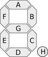
Credits
The Seven Segment Digit image is based on this Seven Segment image from Wikimedia Commons.