DC Motor, Getting Started
A DC motor uses a direct current power source to generate torque. It is commonly used in CPU fans, robots as wheels, toys, CD drives, etc. The DC Motor Board from Zilogic can be used to control a DC motor’s speed and direction of rotation. In this first article, in a series of articles on the DC Motor Board, we will introduce the reader to the theory behind the working and control of a DC motor.
Basic H-Bridge Operation
The H-Bridge is an electronic circuit that allows voltage to be applied to a motor in either direction, and thus control the direction of rotation of the motor. A simple H-Bridge constructed using switches is shown in the following diagram. By controlling, the switches the motor can be made to rotate forward, reverse, brake, and free run. The various switch states and their effect on the motor is shown in the following table.
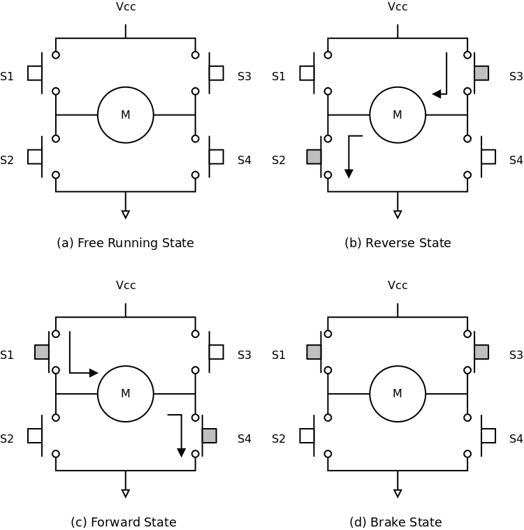
-----|--------|---------|-----------|------------------ S1 | S2 | S3 | S4 | Function
0       0       0       0       Free-run
0       1       1       0       Reverse
1       0       0       1       Forward
0       1       0       1       Brake
1 0 1 0 Brake- Forward
-
The current flows in one direction through the motor.
- Reverse
-
The current flows in the opposite direction through the motor.
- Brake
-
Applying same voltage to both the terminals, counters the back EMF produced by the motor, and causes it to come to a sudden stop.
- Free-run
-
Power is cut-off from the motor, and the motor free-runs and eventually stops.
To control the motor through digital / PWM signals, the switches are replaced by transistors / MOSFETs. Driver ICs like the Si9986, A3901, L298, etc. that implement the H-Bridge can also be used for motor control applications.
Motor Control
The DC Motor Board has a H-bridge motor driver IC, Si9986. By controlling the inputs, various functions can be selected, as shown in the table below.
PWM0
|
PWM1
|
Function |
|---|---|---|
| 0 | 0 | Brake |
| 1 | 0 | Forward |
| 0 | 1 | Reverse |
| 1 | 1 | Free-run |
When in Forward state or Reverse state, the speed of the motor can be controlled by driving the inputs with a PWM signal
PWM0 Duty
|
PWM1 Duty
|
Function |
|---|---|---|
| 0% | 0% | Brake |
| 100% | 100% | Free-run |
| 0% | 100% | Reverse, full speed |
| 100% | 0% | Forward, full speed |
| X% | 100% | Reverse, speed inversely proportional to duty cycle |
| 100% | X% | Forward, speed inversely proportional to duty cycle |
Credits
The DC Motor icon is based on the original image located here, at Wikimedia Commons.