Audio Board, Getting Started
Embedded systems generally use an audio interface for alert beeps and notifications. The Audio Board from Zilogic, extends a motherboard, with audio capabilities. Using the Audio Board, requires knowledge on the following:
-
Representation of audio data in a computer.
-
Conversion of audio data into a sound/audio signal.
In this first article, in a series of articles on the Audio Board, we will introduce the reader to audio fundametals, and usage of the Audio Board.
Audio Basics
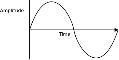
An audio signal when captured through a microphone is available as a time varying voltage, as shown in [signal]. When such signals are to be stored in a computer, they have to be digitized. The digitization is a two step process.
-
Sampling
-
Quantization
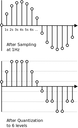
A time varying voltage signal, has infinite no. of values between two
time points, say second 0 and second 1. As such it is impossible to
store these values in a computer. Instead we approximate the signal by
looking at the signal periodically, say every 10ms. We note the
voltage at 0ms, 10ms, 20ms, 30ms and so on. An example is shown in
[sampling-quantization]. This way of storing only specific time
points of a signal is called Sampling. If the sampling period is T,
1/T is called the Sampling Frequency.
The only restriction on the sampling frequency, is that, the sampling frequency should be twice the maximum frequency in the signal, for the signal to be completely reproduced.
A time varying voltage signal, that varies between say -3V and 3V, has infinite no. of values between -3V and 3V. Here again we restrict ourselves to a set of values that are equally spaced between -3V and 3V. For example, we might choose a spacing of 1V, and hence will store only -3V, -2V, -1V, 0V, 1V, etc. If at a time point we read a value of 0.8V, then we round if off to 1V, and store 1V instead. Each of these voltages is given a binary representation, as shown in the following table. It is this binary representation that actually gets stored.
| Voltage | Binary Representation |
|---|---|
-3V |
001 |
-2V |
010 |
-1V |
011 |
0V |
100 |
1V |
101 |
2V |
110 |
3V |
111 |
This way of restricting ourselves to a set of values, is called Quantization. The no. of values we restrict ourselves to determines the accuracy with which the signal has been captured, and the accuracy with which it can be reproduced. The more the no. of levels more the no. of bits required to represent each sample. The no. of bits required to represent a sample is called the Bit Depth or Bits Per Sample.
The following table indicates the sampling frequency and the audio bit depth, for various different audio quality.
| Quality | Sampling Frequency | Bits Per Sample |
|---|---|---|
Telephone |
8KHz |
8 |
AM Audio |
11.025KHz |
8 |
FM Audio |
22.050KHz |
16 |
CD |
44.1KHz |
16 |
DVD |
48KHz |
16 |
Compression
A five minute stereo audio signal stored in CD quality, will occupy about 50 MB. Fortunately, audio data can easily be compressed. An MP3 or OGG compression will result in just 5 MB of compressed data. Uncompressed audio is generally called PCM. And when such PCM data is stored in a file without any headers, it is called a Raw PCM file.
Creating Raw PCM
Audio is generally stored in a compressed format like MP3. But these need to be converted to Raw PCM before it can be sent to the Audio Board. The Audio Board can play audio with the following parameters:
-
Bits Per Sample: 8
-
Sampling Frequency: 8kHz
-
Channels: 1
A Raw PCM file with these parameters can be created using tools like SOund eXchange (SOX), FFmpeg, etc.
Pseudocode Functions
The pseudocode presented in the following sections, assume the existence of the following functions:
-
spi_tx_rx(byte) -
Transmits an 8-bit integer
byteto the SPI device, and returns the received byte as an 8-bit integer. -
gpio_set_pin(pin, state) -
Sets the state of an GPIO pin to high or low.
pinis an integer, representing the GPIO pin no.stateis an integer, 0 for low and 1 for high. The pin should have previously been configured to output mode. -
udelay(usecs) -
Generates a delay.
usecsspecifies the delay in microseconds.
Playing Raw PCM
The Raw PCM audio created using the instruction in [raw-pcm] can be stored in Flash memory of a micro-controller. The micro-controller can then play the audio by sending it to the DAC through a SPI interface. The following SPI parameters should be configured
-
Transmit data on falling edge of the clock.
CPOL= 0,CPHA= 0 orCPOL= 1,CPHA= 1. -
Transmit data bytes MSB first.
The following is the pseudocode to play a sample from the 8KHz 8-bit Raw PCM audio.
play_sample(sample):
gpio_set_pin(CS1, 0)
byte = (sample >> 4) & 0x0F #  byte |= 0x10 #
  spi_tx_rx(byte)
byte = (sample << 4) & 0xF0 #
spi_tx_rx(byte)
byte = (sample << 4) & 0xF0 #  spi_tx_rx(byte)
gpio_set_pin(CS1, 1)
spi_tx_rx(byte)
gpio_set_pin(CS1, 1)
| First byte contains the upper nibble, of the sample. | |
| Bit 4 indicates when set to 1 indicates Active Mode, and when set to 0 indicates Power Down mode. | |
| Second byte contains the lower nibble, of the sample. |
The following is the pseudocode to play a sequence of samples the 8KHz 8-bit Raw PCM audio. The sampling period is 125us for 8KHz audio. Hence we send out one sample every 125us.
play(sample_list):
    for each sample in sample_list:
        play_sample(sample)
        udelay(125)
Using DataFlash for Storage
As discussed earlier, Raw PCM audio data can easily consume lot of space. The Flash memory in micro-controllers is generally not sufficient to store such data. The Audio board provides a 4MB DataFlash for easy storage and retrieval of audio data.
The DataFlash itself is accessed through the SPI interface. Data is organized in a DataFlash in pages. Each page is 528 bytes in size.
The pseudocode to read a page from the DataFlash.
read_page(pageno, data):
gpio_set_pin(CS0, 0) #
spi_tx_rx(0xD2) #
spi_tx_rx((pageno >> 6) & 0xFF) #
spi_tx_rx((pageno << 2) & 0xFF)
spi_tx_rx(0)
spi_tx_rx(0) #  spi_tx_rx(0)
spi_tx_rx(0)
for i in 1 ... 528: #
spi_tx_rx(0)
spi_tx_rx(0)
spi_tx_rx(0)
for i in 1 ... 528: #  data[i] = spi_tx_rx(0)
gpio_set_pin(CS0, 1) #
data[i] = spi_tx_rx(0)
gpio_set_pin(CS0, 1) #
| Chip select is asserted on entry, and deasserted on exit. | |
The first byte transmitted is 0xD2, the DataFlash command to read a
page.
| |
| The next three bytes transmitted, correspond to the page no. and the byte offset (set to 0 here). | |
| The next four bytes transmitted, are dummy bytes, required by the DataFlash to process the command. | |
| The next 528 bytes transmitted, are dummy zero bytes, in return the DataFlash will return 528 bytes that correspond to the page data. |
The pseudocode to write a page to the DataFlash.
write_page(pageno, data):
    gpio_set_pin(CS0, 0)

    spi_tx_rx(0x82)                     #
    spi_tx_rx((pageno >> 6) & 0xFF)     #
    spi_tx_rx((pageno << 2) & 0xFF)
    spi_tx_rx(0)                        #

    for i in 1 ... 528:                 #
        spi_tx_rx(data[i])

    gpio_set_pin(CS0, 1)

    wait_ready()
The first byte transmitted is 0x82, the DataFlash command to
write a page.
| |
| The next three bytes transmitted, correspond to the page no. and the byte offset (set to 0 here). | |
| The next 528 bytes transmitted, are the bytes to be written to the page. | |
| After the data is written to a page, the uC must wait till the DataFlash is ready to accept more commands. |
wait_ready():
    gpio_set_pin(CS0, 0)

    spi_tx_rx(0xD7)                     #

    ready = (spi_tx_rx(0) & 0x80        #
    while ready == 0:
          ready = spi_tx_rx(0) & 0x80

    gpio_set_pin(CS0, 1)
The first byte transmitted is 0xD7, the DataFlash command to
check if the read the device status.
| |
| Dummy bytes are transmitted, till the device responds with a status byte, with the most significant bit set to 1, indicating the DataFlash is ready to accept more commands. |
Concluding Notes
Hope this tutorial has helped the novice to come up to speed with the Audio Board. In the upcoming articles, in this series, we will provide sample code, showing how to use the Audio Board from ZDev and NuttX.
Credits
-
The headset icon is from Android Style Honeycomb Icons, at IconArchive