Graphics LCD Interfacing With 8051
It may require some graphics image to be displayed in 8051 based products through a monochrome bitmap LCD. This is considered to be a complex task because of its bus interfacing and several command sequence handling. This article explains how a graphics LCD from TIANMA can be connected to a 8051 micro-controller and pixels can be displayed on it with simple steps.
Theory
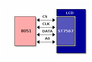
Consider interfacing the TIANMA TM12864J1CCWGWA LCD 128x64 pixels module based on the Sitronix ST7567 lcd controller with NXP’s P89V664 8051 micro-controller. The LCD module provides SPI interface to host(micro-controller) communication. We can use GPIO pins of micro-controller to interface with LCD module instead of SPI pins of micro-controller for convenience. We may need to bitbang the data through gpio lines to get the SPI communication over gpio.
Description
The LCD module has a internal memory and a control circuitary, to map the pixel information from the internal memory to LCD display. The internal memory and control circuitary can be accessed by the micro-controller through the SPI bus. The communication to LCD module from the micro-controller are classified as two type of transaction modes as described below.
Control Mode |
This supports sending commands to intialize and configure the LCD parameters. |
Data Mode |
This supports sending the pixel information to be displayed in the LCD |
The LCD module need to be configured and initialized with a set of commands by the micro-controller. These commands has to be sent to the LCD module one by one in sequence. The sequence can be found in the data sheet of LCD module.
The mandatory control commands to initialize the LCD are listed below.
START_LINE |
to set the start line of the display |
INVERSE |
to inverse 1’s to 0’s and 0’s to 1’s pixel buffer |
COM |
to change the pixel orientation from left to right or right to left |
SEG |
to change the pixel orientation from top to bottom or bottom to top |
PWR_CTRL |
to enable internal power controllers |
RR & EV |
to set the display brightness |
DISP_ON |
to enable display |
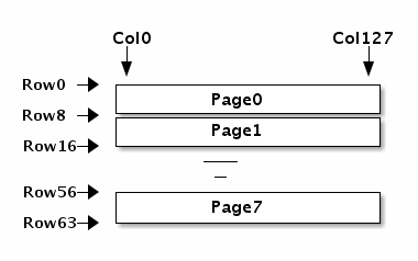
The pixel data should be sent through the bus by choosing the data mode. Before sending a pixel data, we may need to select the exact page and the column where to display the data sent. LCD pixels are organized, such a way that 8 rows are combined as a page, thus forming 8 pages as the LCD supports 64 rows. A 8 bit pixel data sent to LCD module would be displayed in single vertical column, as one pixel in each row of the selected page. The page mapping and byte mapping information can be understood from the below diagrams.
The commands to select the page and column are shown below
PAGE_SEL |
to select one out of 8 pages |
COL_SEL_L/H |
to select one out of 128 columns |
The steps to communicate with the LCD module is described below.
- Sequence to intialize a graphics LCD
-
-
Reset the LCD controller
-
Intialize the power control registers
-
Choose the page, column and orientations
-
Switch the display on
-
- Sequence to write command to a LCD
-
-
Assert chip select
-
Deassert the A0 line to choose command mode
-
Write command through gpio line
-
Deassert the chip select
-
- Sequence to write data to a LCD
-
-
Assert chip select
-
Assert the A0 line to choose data mode
-
Write data through the gpio line
-
Deassert the chip select
-
- Sequence to write pixel data to LCD
-
-
Assert chip select
-
Select page with page selection command
-
Select the columm with column selection command
-
Write the data through the bus
-
Deassert the chip select
-
To have complete display manipulation a buffer has to be maintained in software, if the micro-controller can support a memory of 1 Kile Byte for LCD code, then this can be achieved.
Hardware
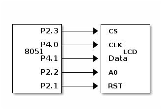
It requires five gpio pins to be connected to the LCD module from the micro-controller.
CS |
Chip select/Enable to the LCD module |
CLK |
clock line to the LCD module |
DATA |
data line to the LCD module |
A0 |
control line to choose between command and data mode |
RST |
To reset the micro-controller |
We have shown a connection interface in the below diagram.
Software
The code for displaying a pixel on the GLCD is given below.
This code has been tested with below tools
-
SDCC
-
P89v664 Micro-controller board
-
LCD module and interface board
NXP’s P89V664 micro-controller has 2 KB of RAM. To enable 2 KB memory, the micro-controller has to be configured for Large Memory Model. You can find the details for configuring Large Memory Model in External Memory HowTo
Source code can be compiled as shown below using SDCC
sdcc --model-large -DCONFIG_LARGE_MEMORY glcd-hw.c
#include <8052.h>

__sfr __at (0xA1) P4;

#define RST      P2_2
#define LCD_RS   P2_1
#define LCD_CS   P2_3
#define LCD_SCL  1
#define LCD_SDA  4
#define PAGE_SEL 0xB0
#define COL_SEL  0x10

#ifdef CONFIG_LARGE_MEMORY
static unsigned char gfx_buf[8][128];

int _sdcc_external_startup()
{
        __sfr __at (0x8E) AUXR;
        AUXR = 0x0;

        return 0;
}
#endif

void delay(int x)
{
        int n,j;
        for(n = 0; n < x; n++)
                for(j = 0; j <= 50; j++);

}

void glcd_write_data(unsigned char dat)
{
        unsigned char maskdata = 0x80;

        LCD_CS = 0;
        LCD_RS = 1;

        while (maskdata) {
                P4 = P4 & ~LCD_SCL;

                if (dat & maskdata)
                        P4 = P4 | LCD_SDA;
                else
                        P4 = P4 & ~LCD_SDA;

                maskdata >>= 1;
                delay(200);
                P4 = P4 | LCD_SCL;
        }

        LCD_CS = 1;

}

void glcd_write_cmd(unsigned char cmd)
{
        unsigned char maskdata = 0x80;

        LCD_RS = 0;
        LCD_CS = 0;

        while (maskdata) {

                P4 = P4 &  ~LCD_SCL;

                if (cmd & maskdata)
                        P4 = P4 | LCD_SDA;
                else
                        P4 = P4 & ~LCD_SDA;

                maskdata >>= 1;
                delay(2);
                P4 = P4 | LCD_SCL ;

        }
        LCD_CS = 1;
}

void glcd_init(void)
{
        RST = 0;
        delay(1000);
        RST = 1;

        glcd_write_cmd(0xE2);            // S/W RESWT
        glcd_write_cmd(0xA3);            // LCD bias
        glcd_write_cmd(0xAF);            // Display ON
        glcd_write_cmd(0xA0);            // segment direction.
        glcd_write_cmd(0xC8);            // Common Direction.
        glcd_write_cmd(0x22);            // Regultion resistor select  //25
        glcd_write_cmd(0x81);            // EV Select.
        glcd_write_cmd(0x2f);            // Select EV value.
        glcd_write_cmd(0x2f);            // Power control


        glcd_write_cmd(0x40);            // Initial display line 40
        glcd_write_cmd(0xB0);            // Set page address
        glcd_write_cmd(0x10);            // Set coloumn addr  MSB
        glcd_write_cmd(0x00);            // Set coloumn addr LSB
        glcd_write_cmd(0xAF);            // Display ON
        glcd_write_cmd(0xA4);            // A5 .Normal display, all pixels OFF.
        glcd_write_cmd(0xA6);            // A7 .Normal display (Inverse Pixel)
}

void glcd_set_pixel(int x, int y, int color)
{
        int page,col;
        int row_in_page;

        page = y / 8;

        /* Selecting Page */
        glcd_write_cmd(PAGE_SEL | page);

        /* Selecting Column */
        col = ((x & 0xF0) >> 4) | 0x10;
        glcd_write_cmd(COL_SEL|col);
        glcd_write_cmd(x & 0xf);

        /* Pixel location */
        row_in_page = y % 8;

#ifdef CONFIG_LARGE_MEMORY
        if (color)
                gfx_buf[page][col] |= 1 << row_in_page;
        else
                gfx_buf[page][col] &= ~(1 << row_in_page);

        glcd_write_data(gfx_buf[page][col]);
#else
        if (color)
                glcd_write_data(1 << row_in_page);
#endif

}

int main()
{
        int i = 0, j = 0;

        glcd_init();

        for (i = 0; i < 128; i++)
                for (j = 0; j < 64; j++)
                        glcd_set_pixel(i, j, 1);
        return 0;
}